|
|
CDMA TECHNOLOGIES |
|
ECE DEPTT.
|
 HOME
HOME
|
|
HOD'S DESK |
|
ECE FACULTY |
|
PLACEMENT CELL |
|
SYLLABUS |
|
NOTICE BOARD |
|
CLASS BULLETIN |
|
CONFLUENCE |
|
SEMINAR REPORTS |
|
ALUMNI SECTION |
|
COMING UP... |
|
YOUR VIEWS |
|
Multiple Access Techniques Multiple access schemes are used to allow many simultaneous users to use the same fixed bandwidth radio spectrum. In any radio system, the bandwidth that is allocated to it is always limited. For mobile phone systems the total bandwidth is typically 50 MHz, which is split in half to provide the forward and reverse links of the system.
Sharing of the spectrum is required in order increase the user capacity of any wireless network. FDMA, TDMA and CDMA are the three major methods of sharing the available bandwidth to multiple users in wireless system.
For systems using Frequency Division Multiple Access (FDMA), the available bandwidth is subdivided into a number of narrower band channels. Each user is allocated a unique frequency band in which to transmit and receive on. During a call, no other user can use the same frequency band. Each user is allocated a forward link channel (from the base station to the mobile phone) and a reverse channel (back to the base station), each being a single way link. The transmitted signal on each of the channels is continuous allowing analog transmissions. The channel bandwidth used in most FDMA systems is typically low (30kHz) as each channel only needs to support a single user. FDMA is used as the primary subdivision of large allocated frequency bands and is used as part of most multi-channel systems. Figures below show the allocation of the available bandwidth into several channels. 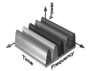 FDMA showing that the each narrow band channel is allocated to a single user 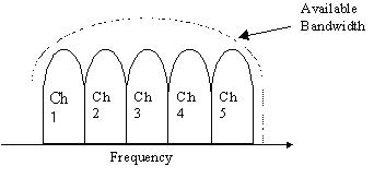 FDMA spectrum, where the available bandwidth is subdivided into narrower band channels 2. Time Division Multiple Access Time Division Multiple Access (TDMA) divides the available spectrum into multiple time slots, by giving each user a time slot in which they can transmit or receive. Figure 8 shows how the time slots are provided to users in a round robin fashion, with each user being allotted one time slot per frame. 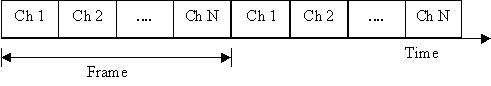 TDMA scheme where each user is allocated a small time slot TDMA systems transmit data in a buffer and burst method, thus the transmission of each channel is non-continuous. The input data to be transmitted is buffered over the previous frame and burst transmitted at a higher rate during the time slot for the channel. TDMA can not send analog signals directly due to the buffering required, thus is only used for transmitting digital data. TDMA can suffer from multipath effects as the transmission rate is generally very high, resulting in significant inter-symbol interference. TDMA is normally used in conjunction with FDMA to subdivide the total available bandwidth into several channels. This is done to reduce the number of users per channel allowing a lower data rate to be used. This helps reduce the effect of delay spread on the transmission. Figure 9 shows the use of TDMA with FDMA. Each channel based on FDMA, is further subdivided using TDMA, so that several users can transmit of the one channel. This type of transmission technique is used by most digital second generation mobile phone systems. For GSM, the total allocated bandwidth of 25MHz is divided into 125, 200kHz channels using FDMA. These channels are then subdivided further by using TDMA so that each 200kHz channel allows 8-16 users [13]. 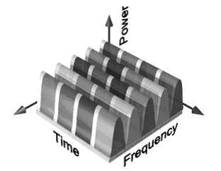 TDMA / FDMA hybrid, showing that the bandwidth is split into frequency channels and time slots 3. Code Division Multiple Access
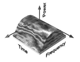
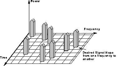
Code Division Multiple Access (CDMA) is a spread spectrum technique that uses neither frequency channels nor time slots. With CDMA, the narrow band message (typically digitised voice data) is multiplied by a large bandwidth signal that is a pseudo random noise code (PN code). All users in a CDMA system use the same frequency band and transmit simultaneously. The transmitted signal is recovered by correlating the received signal with the PN code used by the transmitter. Figure shows the general use of the spectrum using CDMA.
Introduction to CDMA Basics
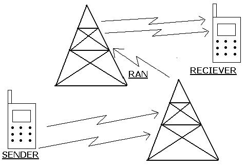
The whole CDMA technology is utilized only in a small portion of the whole procedure of Tele Communication network. This technology is used only when the network interacts with the subscriber or the subscriber interacts with the network. First of all we must learn how does the subscriber interacts with the network.
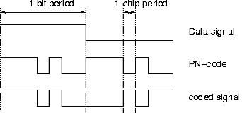
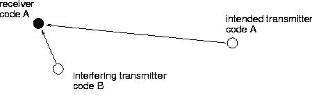
In this section we will discuss only the first and last sets of processes. The details of RAN are discussed in next section. The principles of Spread Spectrum communication In Code Division Multiple Access (CDMA) systems all users transmit in the same bandwidth simultaneously. Communication systems following this concept are ``spread spectrum systems''. In this transmission technique, the frequency spectrum of a data-signal is spread using a code uncorrelated with that signal. As a result the bandwidth occupancy is much higher then required. The codes used for spreading have low cross-correlation values and are unique to every user. This is the reason that a receiver which has knowledge about the code of the intended transmitter, is capable of selecting the desired signal.
In CDMA the transmission bandwith is much larger than the information bandwith.there are various modulation & demodulation techniques utilized in Telecommunication technology. First of all let us get familier with the term modulation & demodulation: Modulation is the process of varying a carrier signal in order to use that signal to convey information. The three key parameters of a sinusoid are its amplitude, its phase and its frequency, all of which can be modified in accordance with an information signal to obtain the modulated signal. There are several reasons to modulate a signal before transmission in a medium. These include the ability of different users sharing a medium (multiple access), and making the signal properties physically compatible with the propagation medium. In analog modulation, the change is applied continuously in response to the data signal.As in the below diagram the change in the signal is reflected as the change in the frequency of the carrier signal. this is called frequency modulation. 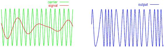 FREQUENCY MODULATION(FM) Modulation is generally performed to overcome signal transmission issues such as to allow · Easy (low loss, low dispersion) propagation as electromagnetic waves · Multiplexing — the transmission of multiple data signals in one frequency band, on different carrier frequencies. · Smaller, more directional antennas Carrier signals are usually high frequency electromagnetic waves. Demodulation is the act of removing the modulation from an analog signal. To demodulate an AM signal, pass it through a diode rectifier. The amplitude variation will integrate into the original modulating signal. There are several ways to demodulate an FM signal. The most common is to use a discriminator. This is composed of an electronic filter which decreases the amplitude of some frequencies relative to others, followed by an AM demodulator. If the filter response changes linearly with frequency, the final analog output will be proportional to the input frequency, as desired. Another one is to use two AM demodulators, one tuned to the high end of the band and the other to the low end, and feed the outputs into a difference amp. Another is to feed the signal into a phase-locked loop and use the error signal as the demodulated signal. A device that performs modulation is known as a modulator and a device that performs the inverse operation of demodulation is known as a demodulator. A device that can do both operations is a modem (a contraction of the two terms).
. Modulating the information signal with the spreading PN sequence. . Modulating the resulting signal with the desired carrier wave. . Band Pass filtering the output and transmitting the resulting RF signal. Receiving a Spread Spectrum Signal involves the following steps: . Demodulating the signal with the RF carrier. . Low Pass Filtering the resulting wide band signal. . Demodulating the signal with the known spreading sequence and integrating the despread signal over a bit rate to recover the information signal. The figure below shows the series of steps that are follwed after the signal has reached the tower from the mobile and before the signal comes to the mobile from the tower. The process of decoding and interleaving also takes place in the mobile set itself. Interleaving in computer science is a way to arrange data in a non-contiguous way in order to increase performance. 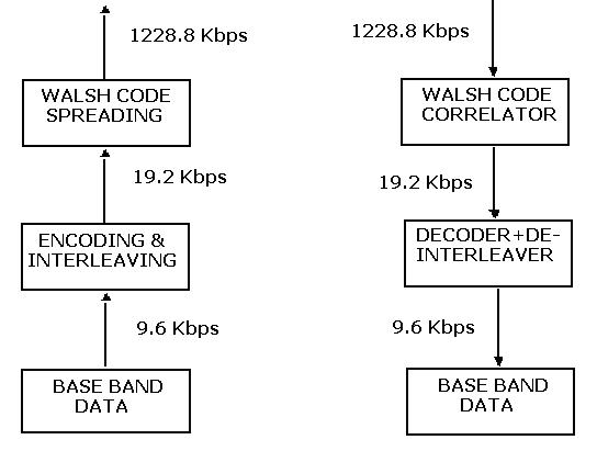 Pseudo-Noise Sequences So far we haven't discussed what properties we would want the spreading signal to have. This depends on the type of system we want to implement. Let's first consider a system where we want to use spread spectrum to avoid jamming or narrow band interference. If we want the signal to overcome narrow band interference, the spreading function needs to behave like noise. Random binary sequences are such functions. They have the following important properties:
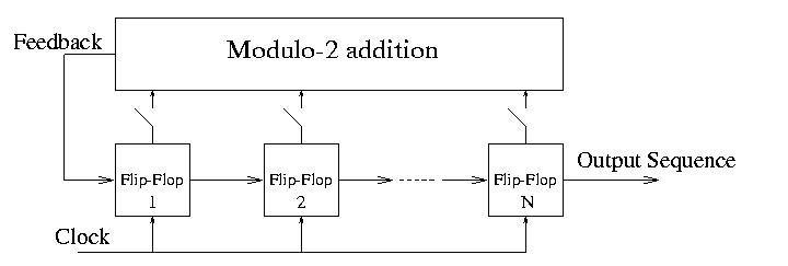 The maximum length of a PN sequence is determined by the length of the register and the configuration of the feedback network. An N bits register can take up to 2N different combinations of zeros and ones. Since the feedback network performs linear operations, if all the inputs (i.e. the content of the flip-flops) are zero, the output of the feedback network will also be zero. Therefore, the all zero combination will always give zero output for all subsequent clock cycles, so we do not include it in the sequence. Thus, the maximum length of any PN sequence is 2N-1 and sequences of that length are called Maximum-Length Sequences or m-sequences. They are useful because longer sequences have better properties. PN sequences are therefore periodic noise like binary functions generated by a network of feedback loops, modulo-2 adders and flip-flops. Maximum length PN functions have a period of 2N-1. The Walsh code is used to uniquely define individual communication channels. Walsh codes are orthogonal mathematical codes. As such, if two Walsh codes are correlated, the result is intelligible only if these two codes are the same. As a result, a Walsh-encoded signal appears as random noise to a CDMA capable mobile terminal, unless that terminal uses the same code as the one used to encode the incoming signal. Walsh-sequences have the advantage to be orthogonal, in this way we should get rid of any multi-access interference. CDMA is interference limited multiple access system. Because all users transmit on the same frequency, internal interference generated by the system is the most significant factor in determining system capacity and call quality. The transmit power for each user must be reduced to limit interference, however, the power should be enough to maintain the required Eb/No (signal to noise ratio) for a satisfactory call quality. Maximum capacity is achieved when Eb/No of every user is at the minimum level needed for the acceptable channel performance. As the MS moves around, the RF environment continuously changes due to fast and slow fading, external interference, shadowing, and other factors. The aim of the dynamic power control is to limit transmitted power on both the links while maintaining link quality under all conditions. The "Magic" of CDMA CDMA offers an answer to the capacity problem. The key to its high capacity is the use of noise-like carrier waves. Instead of partitioning either spectrum or time into disjoint "slots" each user is assigned a different instance of the noise carrier. While those waveforms are not rigorously orthogonal, they are nearly so. Practical application of this principle has always used digitally generated pseudo-noise, rather than true thermal noise. The basic benefits are preserved, and the transmitters and receivers are simplified because large portions can be implemented using high-density digital devices. The major benefit of noise-like carriers is that the system sensitivity to interference is fundamentally altered. Traditional time or frequency slotted systems must be designed with a reuse ratio that satisfies the worst-case interference scenario, but only a small fraction of the users actually experience that worst-case. Use of noise-like carriers, with all users occupying the same spectrum, makes the effective noise the sum of all other-user signals. The receiver correlates its input with the desired noise carrier, enhancing the signal to noise ratio at the detector. The enhancement overcomes the summed noise enough to provide an adequate SNR at the detector. Because the interference is summed, the system is no longer sensitive to worst-case interference, but rather to average interference. Frequency reuse is universal, that is, multiple users utilize each CDMA carrier frequency. The reuse pattern is 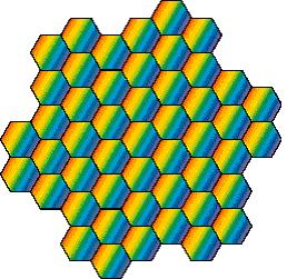 The rainbow cells indicate that the entire 1.25 MHz passband is used by each user, and that same passband is reused in each cell. Multipath Propagation System capacity, as you might expect, is affected by propagation phenomena. Users of analog cellular phones are familiar with the fading that is so annoying, especially in handheld portables when standing nearly still. Fading in a moving vehicle is more rapid, being caused by motion of the vehicle through stationary interference patterns, where the spatial scale of the interference pattern is the wavelength, about one foot. CDMA is much more robust than the analog technologies in the presence of multipath, but it does affect capacity. There are two questions that one must address regarding multipath fading and CDMA. First, under what circumstances will CDMA experience fading, and second, what is the effect of fading, when it occurs, on the CDMA channel? 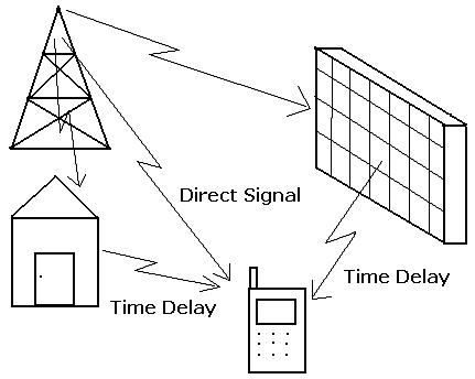 When does multipath cause fading, and when does it not? When the multipath components are "resolved" by the CDMA waveform, that is, when their delays are separated by at least the decorrelation time of the spreading, then they can be separated by the despreading correlator in the receiver. They do not interfere because each component correlates at a different delay. When the multipath components are separated by less than the decorrelation time, then they cannot be separated in the receiver, and they do interfere with one another, leading to what is sometimes called flat fading. The duration of one spreading chip is 1/1.2288MHz = 814 ns, or at the speed of light, 244 meters. Multipath differences less than this will lead to flat fading; greater will lead to resolved multipath, which will be diversity combined by the receiver. To address the second question, that of the effects of fading, the answer is complex and is different in the forward and reverse links. It also depends on the fading rate, which in turn depends on the velocity of the mobile station. Generally fading increases the average SNR needed for a particular error rate. The increase can be as much as perhaps 6 dB. In the reverse link, the power control will mitigate the effects of fading at low speed; at high speed it has little effect. At high speed, and in both links, the interleaving becomes more effective as the characteristic fade time becomes less than the interleaver span. RAKE RECEIVERS One of the main advantages of CDMA systems is the capability of using signals that arrive in the receivers with different time delays. This phenomenon is called multipath. FDMA and TDMA, which are narrow band systems, cannot discriminate between the multipath arrivals, and resort to equalization to mitigate the negative effects of multipath. Due to its wide bandwidth and rake receivers, CDMA uses the multipath signals and combines them to make an even stronger signal at the receivers. CDMA subscriber units use rake receivers. This is essentially a set of several receivers. One of the receivers (fingers) constantly searches for different multipaths and feeds the information to the other three fingers. Each finger then demodulates the signal corresponding to a strong multipath. The results are then combined together to make the signal stronger. 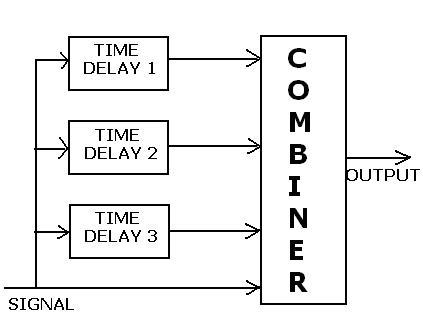 Forward Link & Reverse Link: There are separate names given and frequencies allotted to the accesses from the tower to the mobile and from the mobile to the tower.
Two different types of signals or channels may be transmitted on the reverse link in IS-95 systems. These signal types are the Access Channels and the traffic channels. There can be as many as 32 Access Channels per paging channel associated with any one pilot. The number of reverse-link traffic channels is generally determined by the system self-interference. The total number of reverse-link channels supporting calls in progress equals the total number of forward-link traffic channels also supporting the same number of calls. Therefore, the number of traffic channels cannot exceed 63, the maximum number of Walsh words available to traffic, even though there are many more than this number of long code offsets which uniquely identify the individual Access Channels and mobile users. 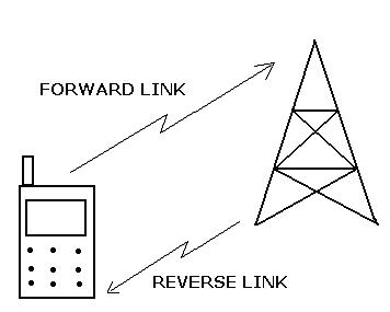 MIN1 and MIN2 The Mobile Identification Number (MIN) is a 34-bit number that is derived from the 10-digit directory telephone number assigned to a mobile station. The rules for deriving the MIN from the 10-digit telephone number are given in the IS-95 standard. MIN1 is the first or least significant 24 binary digits of the MIN. MIN2 is the second part of the MIN containing the 10 most signif-icant binary digits. MIN1, and the ESN, along with other digital input, are used during the authentication process. The MIN is used to identify a mobile station. Access Channels Now to make contact with the subscriber there are various access channels that are used in CDMA. First let us define what are access channels. An access channel is a mobile-to-base communications channel used primarily for control and sending short messages such as call origination, page response, and registration. Application: In CDMA, up to 32 Access Channels are associated with the pilot offset of a particular base station. The mobile uses an Access Channel to transmit to a base station when it is not in the traffic mode. Overhead or control data and short messages are sent to the base station at a rate of 4800 bits/second. Mobile transmitting power control and randomized timing are used to control or limit contention, which is the simultaneous reception of access messages at the base station. An Access Channel is identified by its unique long code mask, which in part depends on the pilot offset of the base station to which the mobile is transmitting. After the mobile initially acquires the Pilot of a base station and reads the data on the Synchronization channel, it transmits to the base station on an Access Channel. This is the first indication that the base station has that the mobile is present and active. All communications with the base station occur using the Access Channel until the mobile is placed in the traffic mode. Pilot Channel It is the base-to-mobile forward-link channel which is modulated only by the pilot PN spreading codes common to all signals transmitted from a given base station. Application: The pilot channel provides several critically important functions to the forward links in IS-95 systems. As its definition states, the pilot channel is only modulated by the PN spreading codes. This facilitates the process of generating a time synchronized replica at the receiver of the PN spreading sequences used at the transmitter to modulate the Synchronization, paging, and traffic channels transmitted from that base station. The power of the pilot is an indication to the mobile of its ability to successfully use the signals from the base station transmitting that pilot. The individual pilots are recognizable based on a specific offset of the short pilot PN sequences which have a period of exactly 215 chips. The pilot channel also provides the coherent reference signal needed to demodulate the coherent Binary Phase Shift Keying (BPSK) modulation used on the forward link. The pilot channel, when processed by the pilot searcher, also identifies the multipath-delay structure on which the mobile receiver bases its decisions of how best to use its RAKE-receiver fingers. To provide all these important functions reliably, the power level at which the pilot channel is transmitted is typically higher than the power used on any other channel. A pilot-power level of 2 Watts is not unusual. With a total forward-link power output of say 8 Watts, the pilot power is usually on the order of 25% of the total forward-link power. Paging Channel It is a base-to-mobile forward-link communications channel used to send control, call set-up, and paging messages when the mobile is not in the traffic mode. Application: There are up to 7 paging channels available to each base station. While the mobile is not in the traffic mode, the base sends orders and messages to the mobile on the paging channel. It receives responses and requests via the mobile's Access Channel. The data rate on the paging channels is either 9600 or 4800 bits/sec. The paging traffic is protected by rate 1/2 convolutional encoding, interleaving, and scrambling using a paging channel mask. The nth paging channel, n equal 1 up to 7, is always assigned the nth Walsh word. There is no power control on the paging channel. The pilot PN code offset used to spread the paging channels is the same as used to spread all the other signals transmitted by a given base station. Traffic Channel It is an individual separable signal which carries a primary digital voice message Application: The major purpose of the traffic channels in IS-95 is to carry the primary digital voice messages. However, when a mobile has been assigned to a traffic channel, that channel also carries signaling traffic and, on the forward link, power control bits. The forward link to a particular mobile is identified by a Walsh word assigned to that mobile for use during a call. The forward-link traffic channels use rate 1/2 convolutional encoding, symbol repetition to produce a common symbol stream at a rate of 19.2 ksym/sec, and inter-leaving over a Vocoder frame of 20 msec. The traffic channel is scrambled using a 19.2 chip/sec stream derived by decimating a long PN code generator whose mask belongs to the user to whom the message is being sent. After scrambling for privacy, and possible puncturing by power control bits, the traffic channel is spread using quadrature spreading codes common to every QPSK signal transmitted from a given base station. The power on the for-ward-link traffic channels is controlled based on frame error rate statistics of the forward-link messages which are measured by the mobile and reported to the base station. The power transmitted varies on a frame-to-frame basis depending on the bit rate at the Vocoder output.The reverse link from a mobile to a base station is identified by a long code offset or mask which is permanently assigned to that mobile. The reverse-link traffic channels use rate 1/3 convolutional encoding, symbol repetition to produce a common symbol stream at a rate of 28.8 ksym/sec, and interleaving over a Vocoder frame of 20 msec. The interleaver output is partitioned into 6-symbol blocks used to select one of 64 orthogonal Walsh words. Any duplicate symbols produced by repetition are removed by the data burst randomizer. The bursts out of the data burst randomizer are scrambled using a 1.2288 Mchip/sec stream derived from a long PN code generator with a mask belonging to the mobile user. After scrambling for privacy, the traffic channel is spread using quadrature spreading codes to produce offset or staggered QPSK. The power on the reverse-link traffic channels is controlled based by the open loop, closed loop, and outer loop power control procedures. The forward-link base-to-mobile channel on which the IS-95 Synchronization messages are transmitted. Application: The Synchronization channel carries the Synchronization message at a rate of 1200 bits/sec. The bits are protected by rate 1/2 convolutional encoding, yielding 2400 sym/sec, and then repeated for protection to form a stream at 4800 sym/sec. The 4800 sym/sec stream is interleaved 128 symbols at a time spanning exactly 26.666... msec, which equals the period of the pilot code. Walsh word 32, consisting of 32 binary zeros followed by 32 binary ones is used to identify the Synchronization channel. The 32 zeros and 32 ones of Walsh word 32 may be viewed as a square wave which is zero for about 26.04 µsec and then one for 26.04 µsec. Having a bandwidth of about 38.4 kHz. This signal is then PN spread to the approximate 1.25 MHz of the physical channel by the pilot PN codes. Power control is not used on the Synchronization channel. Antennas Now, having studied about the channels let us concentrate on the Antennas that transmit all these channels from the base station to the mobile station. An antenna or aerial is an electronic component designed to transceive radio signals (and, more generally, other electromagnetic waves). Antennas are for transmission of radio wave energy through the natural media (i.e., air, earth, water, etc.) for point-to-point communication or for the reception of such transmitted radio wave energy. Antennas are primarily designed for transmission of radio wave energy through free space or any space where the movement of energy in any direction is substantially unimpeded, such as interplanetary space (such as the interplanetary medium or interstellar medium), the atmosphere, the ocean (and other large bodies of water), or the Earth. Antennas are used for communicating and conveying information specifically in larger systems, such as the radio, telephone, and the telegraph. 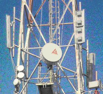 Physically, an antenna is an arrangement of conductors designed to radiate (transmit) an electromagnetic field in response to an applied alternating voltage and the associated alternating electric current, or to be placed into an electromagnetic field so that the field will induce an alternating current in the antenna and a voltage between its terminals. How antennas work Any conducting mass may function as a radiator or collector of radio wave energy and may act as an antenna. Antennas, more specifically, are passive conducting masses, which may be in the form of a metallic current conductor, waveguide, or space discharge. This mass in use is in direct engagement with free space to emit or collect radio wave energy to or from free space, and is coupled or connected to a source of energy or to a load. To act as an antenna, the mass usually has a particular shape and size, or may have electrical circuit elements, namely resistance, inductance, or capacitance, associated with it. "Scanning" an antenna repeatedly moves the antenna beam over an area in space, such as in radar. "Sweeping" an antenna moves the antenna beam repeatedly along a single line (which may be straight or curved) in space. The reactive field: Fundamentally, all electromagnetic fields are created by the existence or movement of electrical charge, and in normal electrical circuits, this charge is exclusively carried by electrons and protons. Since protons tend to be confined within atoms and move very little, it is usually only the movement of electrons that needs to be considered. Since an electric current in a wire consists of a moving cloud of electrons, it follows that every electric current induces a magnetic field. (Every electron also has its own permanent electric field called its coulomb field, but this is not observable outside the circuit because it is canceled by the equal but opposite coulomb field of a nearby proton.) If the current is constant, it induces a constant magnetic field, and the magnetic field is proportional to current. Maxwell's equations predict that a changing magnetic field induces a changing electric field, so we now have both magnetic and electric fields around the circuit, creating an electromagnetic field called the reactive field or inductive field. However, when the current stops, these fields collapse, returning energy to the power supply. The circuit therefore behaves like a reactive component, either a capacitor or an inductor, which stores energy temporarily but periodically returns it to the source. The radiating field: Now consider a current that periodically reverses direction: an alternating current. This consists of a flow of electrons that must therefore reverse direction, and a change of direction is an acceleration. Because of the way that electromagnetic fields propagate through space at the speed of light, an accelerating electrical charge creates electromagnetic radiation. The result is that energy is continually radiated into space, and must be replenished from the circuit's power supply. The circuit is now behaving as an antenna, and is continually converting electrical energy into a radiating field that extends indefinitely outward. When the circuit is much shorter than the wavelength of the signal, the rate at which it radiates energy is proportional to the size of the current, the length of the circuit and the frequency of the alternations. In most circuits, the product of these three quantities is small enough that not much energy is radiated, and the result is that the reactive field dominates the radiating field. When the length of the antenna approaches the wavelength of the signal, the current along the antenna is no longer uniform and the calculation of power output becomes more complex. Practical antennas: Although any circuit can radiate if driven with a signal of high enough frequency, most practical antennas are specially designed to radiate efficiently at a particular frequency. An example of an inefficient antenna is the simple Hertzian dipole antenna, which radiates over wide range of frequencies and is useful for its small size. A more efficient variation of this is the half-wave dipole, which radiates with high efficiency when the signal wavelength is twice the electrical length of the antenna. 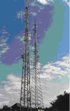 One of the goals of antenna design is to minimize the reactance of the device so that it appears as a resistive load. An "antenna inherent reactance" includes not only the distributed reactance of the active antenna but also the natural reactance due to its location and surroundings (as for example, the capacity relation inherent in the position of the active antenna relative to ground). Reactance diverts energy into the reactive field, which causes unwanted currents that heat the antenna and associated wiring, thereby wasting energy without contributing to the radiated output. Reactance can be eliminated by operating the antenna at its resonant frequency, when its capacitive and inductive reactances are equal and opposite, resulting in a net zero reactive current. If this is not possible, compensating inductors or capacitors can instead be added to the antenna to cancel its reactance as far as the source is concerned. Once the reactance has been eliminated, what remains is a pure resistance, which is the sum of two parts: the ohmic resistance of the conductors, and the radiation resistance. Power absorbed by the ohmic resistance becomes waste heat, and that absorbed by the radiation resistance becomes radiated electromagnetic energy. The greater the ratio of radiation resistance to ohmic resistance, the more efficient the antenna. In telecommunication, a collinear antenna array is an array of dipole antennas mounted in such a manner that every element of each antenna is in an extension, with respect to its long axis, of its counterparts in the other antennas in the array. A collinear array is usually mounted vertically, in order to increase overall gain and directivity in the horizontal direction. When stacking dipole antennas in such a fashion, doubling their number will, with proper phasing, produce a 3 dB increase in directive gain. In Telecommunication Directional Array Antennas are used. There can be upto 12 sectors of the Antenna but usually 3 sectors are used which are aligned at 120degrees to each other as shown below. The number of sectors depends upon the requirement of the coverage area. Omni-directional antennas are not used due to less gain as compared to the Directional Antennas. 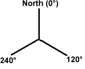 An antenna array-based base station receiver structure for wireless direct-sequence code-division multiple-access (DS/CDMA) with M-ary orthogonal modulation is proposed. The base station uses an antenna array beamformer-RAKE structure with noncoherent equal gain combining. The receiver consists of a “front end” beamsteering processor feeding a conventional noncoherent RAKE combiner. The performance of the proposed receiver with closed loop power control in multipath fading channels is evaluated. The use of an antenna array at a base-station for cellular CDMA is studied. Analysis for a multicell CDMA network with an antenna array at the base-station for use in both base-station to mobile (downlink) and mobile to base-station (uplink) links has modeled the effects of path loss, Rayleigh fading, log-normal shadowing, multiple access interference, and thermal noise, and show that by using an antenna array at the base-station, both in receive and transmit, one can increase system capacity several fold. |